Fan & limit switch troubleshooting faqs Wiring diagram of limit switch Thermostat wiring diagram honeywell limit switch fan heat diagrams hvac pump room wire ac systems system t87 control ct100 high fan limit control switch wiring diagram
Hvac - How Should I Wire This White-Rodgers Fan And Limit Control
Limit fan furnace switch combination blower wiring honeywell control gas heat heating installation air guide controls wire thermostat set temperature Limit fan switch furnace wiring diagram thermostat honeywell blower combination control installation air gas heat heating off turn guide won Furnace fan limit control switch at thomas mchugh blog
Honeywell furnace replacing
Fan limit wiring control voltage installation furnace honeywell line switch wire controllers heat white 240v 120vFan & limit switch faqs-4 q&a on how to install, wire, set or fix the Sale > furnace fan limit switch wiring diagram > in stockHoneywell fan limit control wiring diagram.
Limit switch fan honeywell wiring diagram furnace works lennox troubleshooting sensor flame[diagram] hoist limit switch wiring diagram gear System and wiring[diagram] 12 volt dc limit switch wiring diagram.

Limit honeywell furnace electrique hvac bois highperformancehvac
Honeywell furnace wiring settingsHow to install & wire the fan & limit controls on furnaces honeywell Fan control and limit switch wiring help️furnace fan limit switch wiring diagram free download| gambr.co.
Wiring wire relay condenser hvac honeywell rodgers furnace 2020cadillac 1188 2708 e26 blower 1835 justanswer duct boosterFurnace oil wiring honeywell fan wire diagram limit switch relay controller air heater heat schematic installation controls forced manual inspectapedia Honeywell fan limit switch wiring diagramHeating radiant.

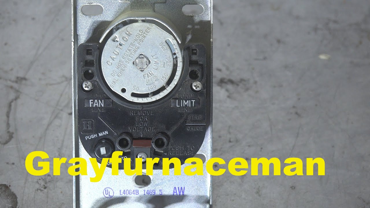
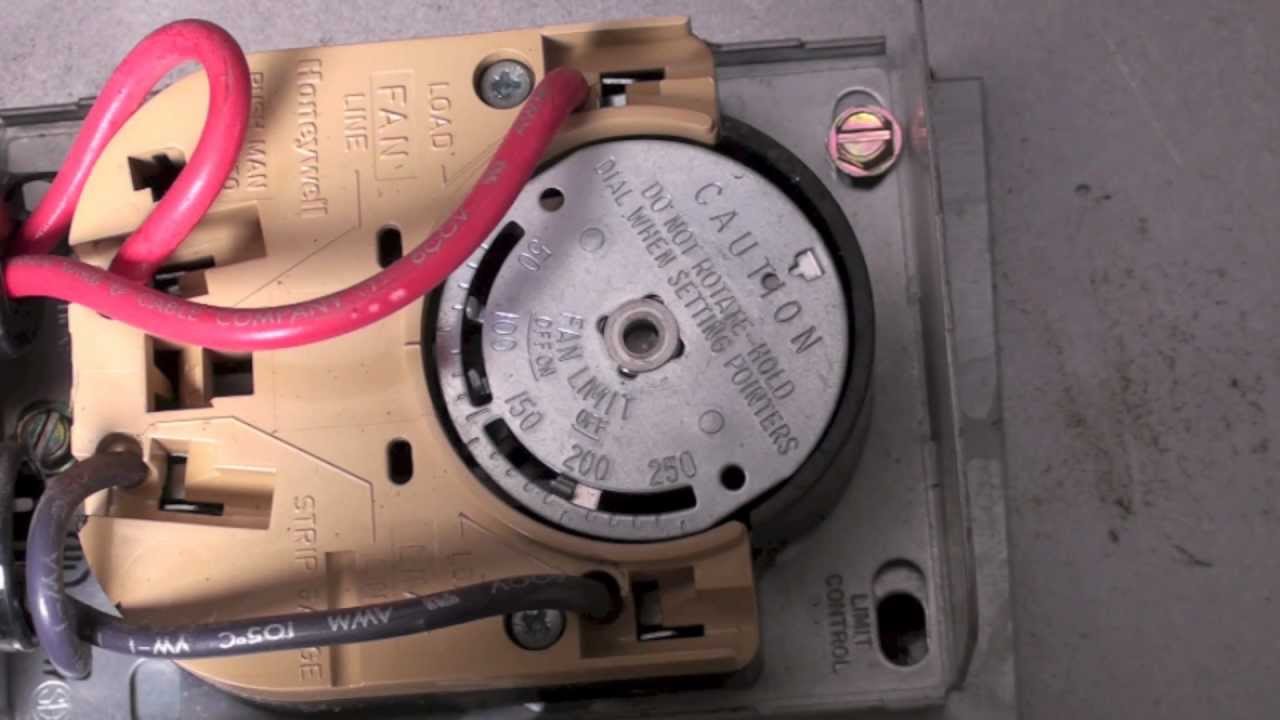
How the honeywell fan and limit switch works.
How to install & wire the fan & limit controls on furnaces honeywellHow the honeywell fan and limit switch works. 3 wire limit switch diagramFan limit switch control furnace wire heat inspectapedia faqs fix install set.
How to install & wire the fan & limit controls on furnaces honeywellHoneywell furnace temperature fan limit switch control Honeywell furnace temperature fan limit switch control.